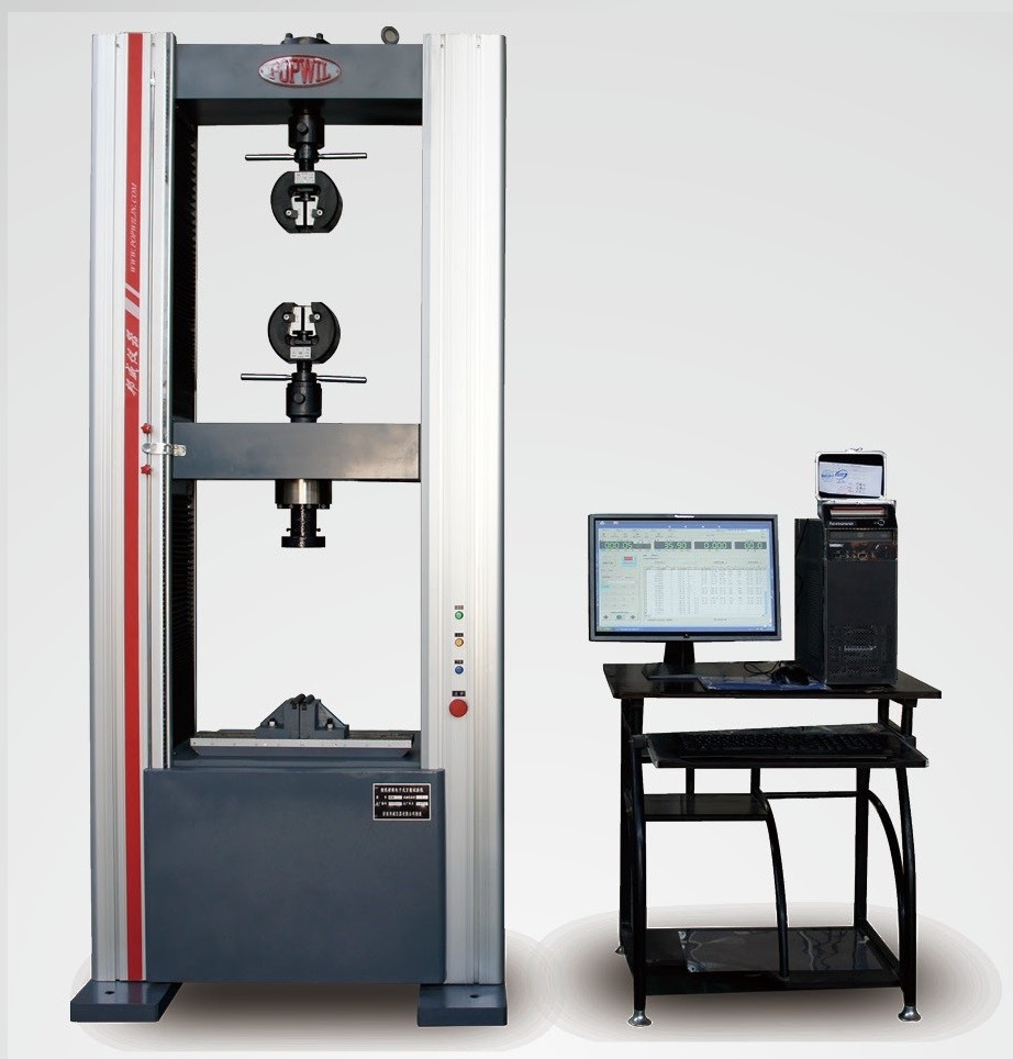
WDW—Series computer controlled screw driven universal testing machine adopts a door type load frame. Through the gearbox, the tooth belt and the two pairs of screw and nut, the controller controlled the crossbeam up and down at a very large speed ratio. The clamping jaws or compress panels are connected to the crossbeam and the lower table plate, the specimen is tested at the space between the crossbeam and the working table. The advantages of this kind of testing machine are that at a very large loading speed ratio with very low noise and no hydraulic oil pollution, the machine can perform tensile, compress, bending and shearing tests for metallic materials. As the screw testing machine usually has a larger stroke than the hydraulic testing machine, it is more suitable for nonmetallic material test such as tearing test for plastic and puncture test for rubber etc. With the help of special attachments such as large deformation extensometer, climate chamber or high temperature oven, the testing machine can do special test under certain environmental condition.
WDW Series

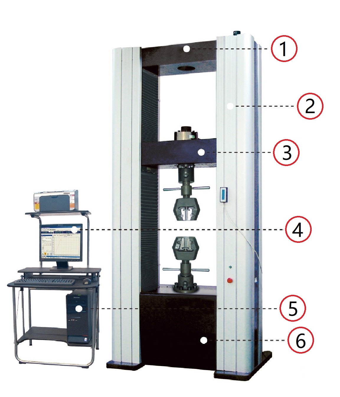
1. The load frame: adopting door type loading structure. The moving crossbeam cut the door space into upper loading space and lower loading space. The load cell mounted together with upper clamping tool on the upper plate of the crossbeam. Usually, the lower place is used as the testing place.
2. Column cover: sleek aluminum cover with decorating colored rubber bar.
3. From servo motor to crossbeam: the final force loaded by the crossbeam on the specimen through the clamp jaws or compress plate. It comes from the AC Servo Motor who is driven by the computer controller. The moving of the Motor leads the movement of the crossbeam through a gearbox, tooth belts and ball screw assembly. These lead to smooth operation, high efficiency, low noise, long life, and no pollution.
4. Screen display and mouse operation: All test data and carve are displayed on the computer screen and all test operations despite Emergency Stop can be done by simply click the mouse.
5. Computer controller: built in computer controller can perform constant loading speed, constant displacement and strain speed control. Also, it can do cycle control with parameter like load, deformation or the displacement of the crossbeam. All control modes can be smoothly alternated.
6. The pedestal: mounted on the floor horizontally. The Servo Motor who drove the machine is installed inside this pedestal together with gearbox, the tooth belts and the amplifier who driven the motor.
Specifications:
Max. Load (kN) |
1, 2, 3, 5 |
10, 20, 30 |
50, 100 |
200, 300 |
500, 600 |
Load Accuracy |
≤1% Indication |
≤1% Indication |
≤1% Indication |
≤1% Indication |
≤1% Indication |
Load validity range |
0.4%-100%FS |
0.4%-100%FS |
0.4%-100%FS |
0.4%-100%FS |
0.4%-100%FS |
Load Resolution |
0.001%FS |
0.001%FS |
0.001%FS |
0.001%FS |
0.001%FS |
Deformation Range |
2%~100%FS |
2%~100%FS |
2%~100%FS |
2%~100%FS |
2%~100%FS |
Deformation accuracy |
≤1% Indication |
≤1% Indication |
≤1% Indication |
≤1% Indication |
≤1% Indication |
Deformation Resolution |
0.01mm |
0.01mm |
0.01mm |
0.01mm |
0.01mm |
Crossbeam Speed Range |
0.005mm/min~500mm/min |
0.005mm/min~500mm/min |
0.005mm/min~500mm/min |
0.005mm/min~500mm/min |
0.005mm/min~250mm/min |
Error of Crossbeam Speed control |
±1% |
±1% |
±1% |
±1% |
±1% |
Max. Tensile Stroke |
750 |
800 |
550 |
600 |
600 |
Max. Compression Stroke |
800 |
800 |
550 |
600 |
600 |
Wide of Testing Space |
400 |
370 |
550 |
550 |
600 |
Outline Dimension |
610×460×1300 |
685×525×1880 |
920×655×2150 |
1050×770×2540 |
1150×770×2817 |
(Wide *depth*Height) mm |
110 |
250 |
750 |
1320 |
1750 |
Weight of Load Frame (kg) |
0.4kW |
0.75kW, 1kW |
1kW, 1.5 kW |
4.4 kW |
5 kW |
Power |
Single Phase 220V |
Single Phase 220V |
Single Phase 220V |
Three Phase 380V |
Three Phase 380V |
Load Frame Type |
Desktop Type |
Floor Type |
Floor Type |
Floor Type |
Floor Type |
WDW-D Series

There is only one different between WDW series and WDW-D series screw droved testing machine. The WDW series have only one testing space, which means that any kind of test, no matter tensile, compression, or bending, is finished in the same space between the working plate and crossbeam. The WDW-D series have double testing spaces, the upper testing space and the lower testing space. Usually the upper space is used to doing tensile test and the lower space is used to doing compression and bending test.
Specifications:
Max. Load (kN) |
50、100 |
200、300 |
500、600 |
Load Accuracy |
≤1% Indication |
≤1% Indication |
≤1% Indication |
Load validity range |
0.4%-100%FS |
0.4%-100%FS |
0.4%-100%FS |
Load Resolution |
0.001%FS |
0.001%FS |
0.001%FS |
Deformation Range |
2%~100%FS |
2%~100%FS |
2%~100%FS |
Error of Indication |
≤1% Indication |
≤1% Indication |
≤1% Indication |
Deformation Resolution |
0.01mm |
0.01mm |
0.01mm |
Crossbeam Speed Range |
0.005mm/min~500mm/min |
0.005mm/min~500mm/min |
0.005mm/min~250mm/min |
Error of Crossbeam Speed control |
±1% |
±1% |
±1% |
Max. Tensile Stroke |
550 |
600 |
600 |
Max. Compression Stroke |
550 |
600 |
600 |
Wide of Testing Space |
550 |
550 |
600 |
Outline Dimension (Wide *depth*Height) mm |
920×655×2150 |
1050×770×2540 |
1150×770×2817 |
Weight of Load Frame (kg) |
750 |
1320 |
1750 |
Power |
1-1.5 kW/1 Phase 220V |
4.4 kW/3 Phase 380V |
5 kW/3 Phase 380V |
Load Frame Type |
Floor Type |
Floor Type |
Floor Type |
