The electro-hydraulic servo controlled structure testing system using self-balance frame is usually used to do the seismic test of typical structure specimen such as columns, beams, plates, walls, frames and joints etc. The size of the frame, the type and number of actuators, the output channels of the controller, and the flow rate of the hydraulic power station can be customized according to the request from the customer.
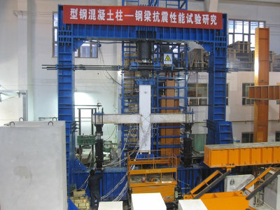
The follow picture and technical specification is one of these special designed structure testing systems using self-balance frame. Beijing University of Civil Engineering and Architecture uses this machine for a special joint specimen test. The maximum load of the vertical loading actuator (column end) is 600t, and the maximum load the of beam end actuators are 200t.

Joint test in Beijing University of Civil Engineering and Architecture
Technical Specifications:
- The main machine adopts a self-balancing rectangular reaction frame, and a beam which connected the top the frame together with the reaction wall in order to improve the horizontal rigidity;
- It is mainly used to do the seismic test of joints, and also can be used to do 3 channels quasi-static loading for other structure tests;
- The maximum test space (length*width*depth) 3000* 3000* 600mm;
- The outline dimension of the loading frame: (length*width* thickness) 8400 * 8430 * 1200mm;
- The column end vertical loading actuator: Press: 600t, Tension: 200t;
- The pseudo static loading actuator at beam end: Press: 200t, Tension: 150t;
- The movable hydraulic power station:
Flow rate:20L/min;
Working pressure: 26mpa;
Air cooling system included; - A POP-M controller with three control channels and worked under application software POPWARE-M;
- The actuator can be replaced by dynamic actuator for fatigue or dynamic test for typical structural specimen such as columns, beams, frames, joints, etc.
- All loading actuators are equipped with load cell or pressure sensors, with effective range 4% - 100% FS, and accuracy ± 1%;
- Stroke of vertical loading actuator: 600mm;
- Stroke of horizontal loading actuator: ± 250mm;
- Each actuator has a built-in displacement sensor with the resolution of 0.01mm;
- Provides ± 8V testing parameter analog output for data acquisition system.
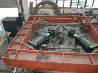
One of the self-balanced frame electro-hydraulic servo controlled structure testing system’s user is The Structure Laboratory of The College of Civil Engineering of Tongji University. It was used in a K-type joint’s load transfer test. The upper arm loading actuator of the K-type joint used the displacement close-loop control to perform step compress loading. The load of the upper actuator was used as the close-loop control target of the pull loading on the lower arm of the K-type specimen. The control target is to keep the press load of upper arm equal to the pull load of the lower arm. The test photos and main technical parameters are as follows:

The testing system was used to do a K-type joint test in Tongji University
Technical Specifications:
- The machine adopts a self balancing rectangular frame as its reaction frame which is specially designed for the load transmission K-joint test.
- Two 2000kN servo actuators are used for loading. The connection type is front ball joint and rear flange.
- Equipped with POP-M dual channel controller and multi-channel application software POPWARE-M to perform closed-loop automatic control of the test.
- Two servo actuators: maximum compression load: 2500kN, maximum tensile load: 2000kN;
- Movable Hydraulic Station:
Nominal flow rate: 10L / min;
Nominal working pressure: 25MPa;
With air cooling system; - The two actuators are equipped with pressure sensors on both front and rear chamber. The output load is measured through measuring the pressure difference between the two chambers.
- Load effective range: 4% - 100% FS;
- Load accuracy: 1% indication value within the effective range;
- Stroke of the loading actuator: ±250mm;
- Each actuator has a built-in displacement sensor with the resolution of 0.01mm;
- Provides ± 8V testing parameter analog output for data acquisition system;
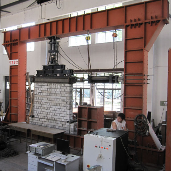
The self-balanced frame electro-hydraulic servo controlled structure testing system designed for Zhejiang University of Technology is a general structural seismic testing system. It can be used to do seismic test for typical structure specimen such as column, beam, wall, frame and joint etc. The follow picture shows the testing system doing a seismic test of a wall type specimen. The vertical loading actuator is fixed on the top crossbeam, and the horizontal loading actuator is fixed on the column. They are controlled by a POP-M controller and POPWARE-M application software. The technical specification of the system shows bellow.

The system using self-balanced frame at Zhejiang University of Technology
Technical Specifications:
- The main machine adopts a vertical installed self balancing reaction frame with rectangular shape;
- The vertical 100t loading actuator with rear flange and front ball joint can be fixed at any suitable place of the upper cross beam;
Maximum compression load: 1200kN;
Maximum tensile load: 1000KN;
Piston stroke: 300mm; - The horizontal 50t loading actuator is a quasi-static actuator with front and rear swivel connectors;
Maximum compression load: 600kN;
Maximum tensile load: 500KN;
Piston stroke:±250mm; - A dual channel POP-M controller operated by the multi-channel application software POPWARE-M to perform a closed-loop automatic controlled structure test.
- Movable Hydraulic Station:
Nominal flow rate: 10L / min;
Nominal working pressure: 25MPa;
With air cooling system; - The two actuators are equipped with load cell and build in displacement sensor.
Load effective range: 4% - 100% FS;
Load accuracy:1% indication value within the effective range;
Displacement resolution: 0.01mm; - Provides ± 8V testing parameter analog output for data acquisition system;
